It's been my dream for a long time to be able to control the lights in my house from anywhere in the world. Now I can do that without breaking the bank. Using a Raspberry Pi, some Etekcity Remote Control Outlets, and a 433 MHz transmitter, I can control the outlets in my home with Siri and any other HomeKit-enabled app on iOS. In this tutorial, I'll show you how to do it too.
- Part 1: Raspberry Pi Print Server
- Part 2: Passwordless SSH on Raspberry Pi
- Part 3: Dynamic DNS with a Raspberry Pi
- Part 4: Home Automation with Siri and a Raspberry Pi
- Part 5: VPN with Raspberry Pi
Unlike the other tutorials in this series, you'll need a few things for this one:
| Required? | Item | Price |
|---|---|---|
| ✓ | Raspberry Pi 3 Model B | $35 USD |
| ✓ | Micro SD Card | $10 USD |
| ✓ | 5V USB Power Supply | $7 USD |
| Raspberry Pi Case | $8 USD | |
| ✓ | Etekcity Remote Control Outlets | $25 USD |
| ✓ | 433 MHz Transmitter and Receiver | $7 USD |
| Total | $92 USD |
Additionally, you'll need some tools and consumables:
| Item | Price |
|---|---|
| 18 AWG Solid Wire | $20 USD |
| Wire Stripper | $5 USD |
| Lead-Free Solder | $5 USD |
| Soldering Iron | $40 USD |
| Female to Female Jumper Wires | $5 USD |
The price of this project is quite cheap if you already have a Raspberry Pi and some basic electronic tools and components: just $32 for the RF outlets and the RF modules! That's downright miserly compared to the cost of buying a commercial, ready-made solution.
This project takes some time to complete, so I recommend you plan to complete this project over the course of several days. I've broken it up into steps with completion milestones to give you good stopping points.
Build Antennae
The RF Transmitter and Receiver need antennae to function really well. Without antennae, their range will be limited to just a few meters. You have a couple choices for your antenna design. The simplest choice is to build a quarter-wave monopole. A quarter wave monopole antenna is just a straight piece of wire that is 25% as long as the wavelength RF signals you're working with.
In this case, the Etekcity outlets operate at 433 MHz. We can find the wavelength of 433 MHz waves with the wave equation
c = f * λ
where c is the speed of light (299,792,458 m/s), f is the frequency of the wave (433,000,000 Hz), and λ is the wavelength of the wave (in meters). Using this equation, we find that our antenna should be 173 mm (or 6-13/16 inches):
299,792,458 = 433,000,000 * λ
λ = 299,792,458 / 433,000,000
λ = 0.69236 m = 692 mm
λ/4 = 173.09 mm
Calculating that was the hard part. To make the antenna, just cut a portion of your 18 AWG wire to the correct length and then strip off about 3 mm (or 1/8 inch) of the insulation. You'll need to do this two times: once for the transmitter and once for the receiver. (I chose 18 AWG wire because it was what I had on hand, it didn't bend easily, and it fit nicely into the ANT holes of the RF modules. The diameter of the wire doesn't really matter, but stiffer is better because the antenna should be straight.)
Once you've made your antennae, solder them into the holes marked ANT on your RF transmitter and receivers.
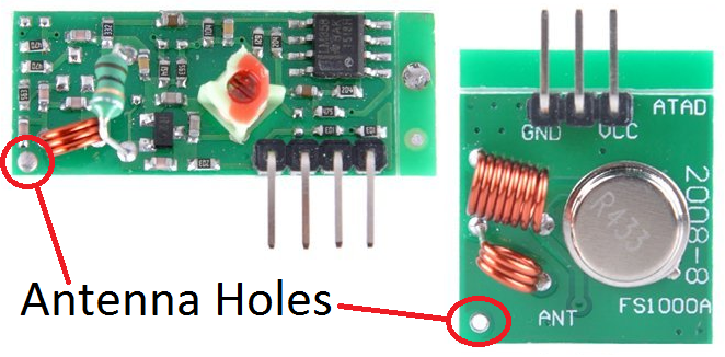
Once you've soldered the antennae to your RF modules, you're done with this step. In the image, I used a different design for my transmitter's antenna called a "coil loaded" antenna. I can't comment on which antenna has better performance, but the coil loaded antenna is slightly more compact.

Connect RF Modules to Raspberry Pi
This step is relatively straightforward. Peel off six jumper wires from your Female to Female Jumper Wires and make the connections in the diagram below.

Here's the same information in a couple tables (the pin locations are described when viewed from the top with the pins on the side closest to you):
| Transmitter Pin Name | DATA | VCC | GND |
|---|---|---|---|
| Transmitter Pin Location | Left | Center | Right |
| Raspberry Pi BCM Pin Number | 17 | 5 V | Ground |
| Raspberry Pi WiringPi Pin Number | 0 | n/a | n/a |
| Raspberry Pi Physical Pin Number | 11 | 2 | 6 |
| Receiver Pin Name | VCC | DATA | GND |
|---|---|---|---|
| Receiver Pin Location | Left | Center (Either) | Right |
| Raspberry Pi BCM Pin Number | 5 V | 27 | Ground |
| Raspberry Pi WiringPi Pin Number | n/a | 2 | n/a |
| Raspberry Pi Physical Pin Number | 4 | 13 | 14 |
Sniff RF Codes
You'll need to find out what codes are sent to turn on and off each of your outlets.
First, update and upgrade your packages and package repositories:
sudo apt update
sudo apt upgrade
Then install Git:
sudo apt install git
Clone and build the WiringPi utility. It's a library that is used by some other programs we'll be using shortly.
cd ~
git clone git://git.drogon.net/wiringPi
cd wiringPi
./build
Now you can compile a couple utilities, codesend and RFSniffer, that let you send and receive data with your 433 MHz RF modules.
cd ~
git clone --recursive git://github.com/ninjablocks/433Utils.git
cd ./433Utils/RPi_utils
make
Next, you can run RFSniffer to find out what codes are assigned to each of your outlets. RFSniffer won't show any output in your console right away. If you press and hold a button on your Etekcity remote, you should see lines like Recieved 5518604 printed in your console.
sudo ./RFSniffer
Make a table showing which codes correspond to which buttons on your remote. The codes for my remote are below. Your codes will be different.
| On | Off | |
|---|---|---|
| 1 | 5510451 | 5510460 |
| 2 | 5510595 | 5510604 |
| 3 | 5510915 | 5510924 |
| 4 | 5512451 | 5512460 |
| 5 | 5518595 | 5518604 |
Once you've created your own table, take a break! You're almost done, and you've completed a good portion of this tutorial.
Confirm RF Codes
Now we can use codesend to confirm our RF codes are correct and our transmitter is functioning correctly.
Plug a lamp into your first outlet, and make sure you can turn it on and off with your remote. Then open up two terminal windows. In the first terminal window, open RFSniffer so you can see the codes that are sent by your remote and the codes that are sent by your transmitter module:
cd ~
cd ./433Utils/RPi_utils
sudo ./RFSniffer
In the second terminal window, you can send some codes to try to turn your outlets on and off. For example, the last line below turns off my first outlet:
cd ~
cd ./433Utils/RPi_utils
sudo ./codesend 5510460 -l 200
5510460 is the code that I got from RFSniffer. the -l argument tells the codesend utility to send the code with a pulse length of 200 us. I was able to control my outlets with pulse lengths between 105 and 1445 us.
You will want to try using different pulse lengths to see what works for your setup. Longer pulse lengths will make it take longer to send a code, but shorter pulse lengths will make it more likely that your code will not be properly received.
I found 200 us to be a good compromise between speed and reliability for me. I'd recommend you use pulse lengths around 200 as well since long pulse lengths can also be unreliable if you get too close to the upper limit for your devices.
After you can successfully turn your outlets on and off with your Raspberry Pi, celebrate! You've completed another milestone in getting your home more automated.
Install Homebridge
Homebridge is a Node.js package that lets you use HomeKit to control devices that weren't designed for HomeKit. We'll use it as he missing link between Siri on iOS and our RF outlets. First, we need to install Node.js:
# setup repo
curl -sL https://deb.nodesource.com/setup_12.x | sudo bash -

# install Node.js
sudo apt install -y nodejs gcc g++ make python net-tools
Confirm that Node and npm are installed correctly by running node -v and npm -v. The output I got is shown below:
$ node --version
v12.22.7
$ npm --version
6.14.15
Install Avahi. Avahi gives Homebridge access to Apple's Bonjour protocol.
sudo apt install libavahi-compat-libdnssd-dev
Finally, Install Homebridge:
sudo npm install -g --unsafe-perm homebridge-config-ui-x
sudo hb-service install --user homebridge

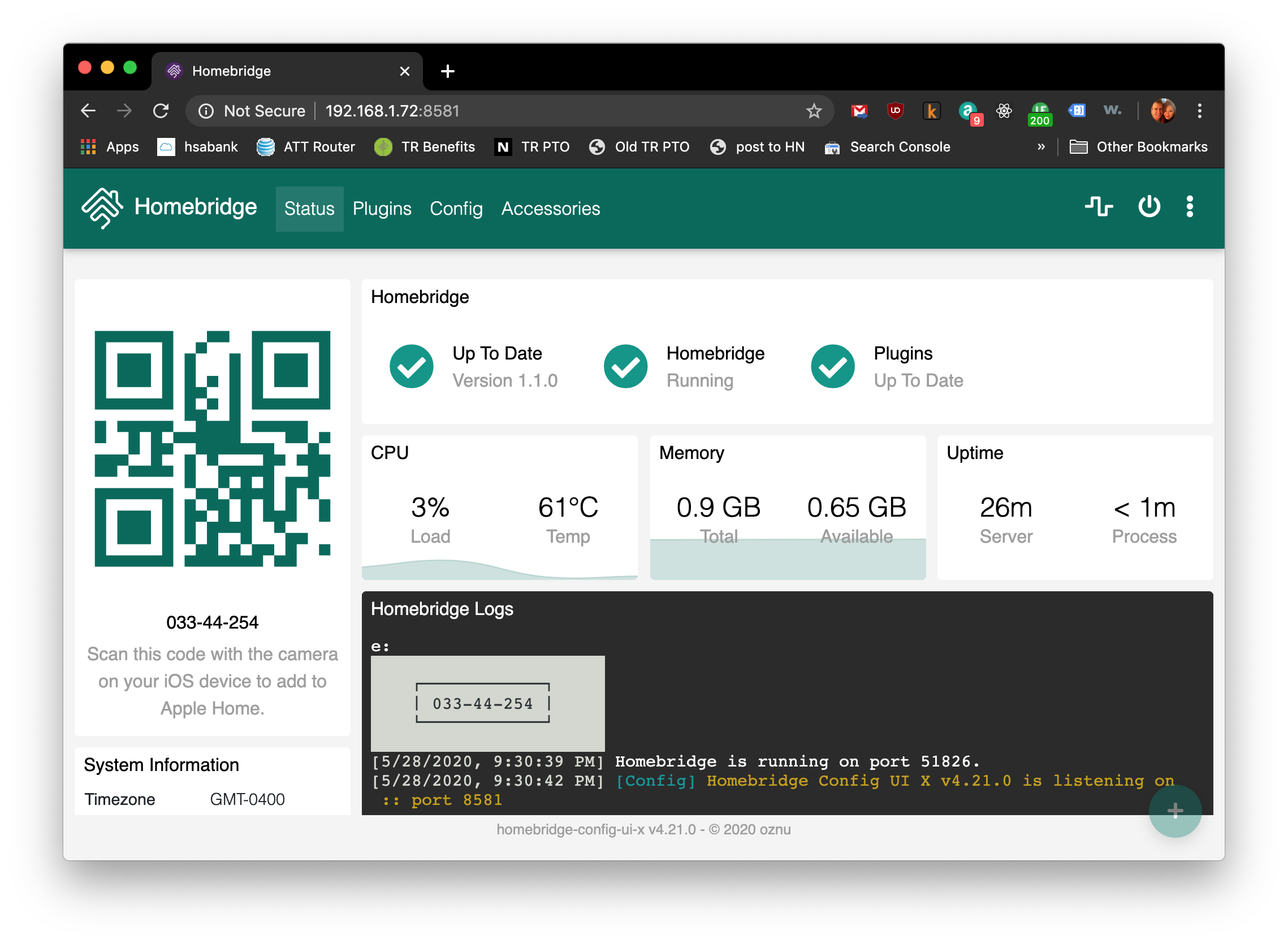
At this point, you can visit the Homebridge GUI in your browser by going to one of the addresses printed out in your console:
Configure a Homebridge Dummy Switch and Pair Your iOS Device
Now we'll add some plugins to Homebridge, configure them, and check to make sure that we can talk to Homebridge from iOS.
First, you need to install a library that is a dependency of the rcswitch plugin we will install later:
sudo apt install libuv-dev
Then install the homebridge-dummy and homebridge-platform-rcswitch-tx-only plugins. You can do that from the Homebridge web interface by clicking "Plugins" at the top of the page, searching for those plugins by name, and clicking "install" for each of them. Here's what your plguins page should look like after you've installed them:

Dummy switches are switches that turn off immediately after you turn them on. They're useful just for checking if your iPhone can talk to your Homebridge.
When you install plugins and platforms, you tell Homebridge what type of devices you want it to be able to talk to. The next step is to tell Homebridge how many of those devices you have, what their names are, and how to talk to them. In other words, we need to configure Homebridge. We do that by modifying Homebridge's config.json file.
Overwrite your Homebridge config.json with Nate Henrie's config.json file:
sudo mkdir -p /etc/homebridge/
sudo wget https://gist.github.com/n8henrie/639c7f5d72b4202cce7e/raw -O /etc/homebridge/config.json
Here's the content of his config.json file, if you're curious:
{
    "bridge": {
        "name": "Homebridge",
        "username": "CC:22:3D:E3:CE:30",
        "port": 51826,
        "pin": "031-45-154"
    },

    "description": "Example config file to test with a homebridge-dummy switch.",

    "accessories": [
        {
            "accessory": "DummySwitch",
            "name": "A dummy switch"
        }
    ]
}
Update the config file through the Homebridge web interface and restart Homebridge.
After you run Homebridge you should get an output that looks something like the image above. Once that happens, open the Home app on your phone. Tap the + button to add an accessory. You will be prompted for a 8-digit PIN. Enter the PIN printed into your console by Homebridge. Or scan the QR code on your Homebridge page.
At this point you should be able to see a single dummy switch that switches itself off immediately after you switch it on. Congratulations! You've reached another milestone in this project. You've linked your Raspberry Pi to your iPhone through HomeKit and Homebridge.
Configure RC Switches in Homebridge
We're almost done. Now we just have to update our config.json file to tell Homebridge that we have RC switches we want it to control, what their names are, and what codes to send to turn them on or off. To get Homebridge to read the updates you're going to make to the config.json file, we'll have to restart Homebridge.
First, update your config.json file through the Homebridge web interface.
I've included my config.json file for your reference. You'll want to change the "pin" value to a new PIN so no one else can control your devices. Also, update the "code" lines with the on and off codes you wrote down earlier. If your Etekcity outlets worked well with a pulse length significantly different than 190, update the "pulse" lines as well with your pulse length
{
  "bridge":{
    "name":"Homebridge",
    "username":"AA:BB:CC:DD:EE:FF",
    "port":51826,
    "pin":"123-45-678"
  },
  "description":"A Homebridge with ten RC switches.",
  "platforms":[
    {
      "platform":"RCSwitch",
      "name":"RCSwitch Platform",
      "send_pin":0,
      "sniffer_pin":2,
      "tolerance":90,
      "switches":[
        {
          "name":"0303-1",
          "on":{
            "code":349491,
            "pulse":200
          },
          "off":{
            "code":349500,
            "pulse":200
          }
        },
        {
          "name":"0303-2",
          "on":{
            "code":349635,
            "pulse":200
          },
          "off":{
            "code":349644,
            "pulse":200
          }
        },
        {
          "name":"0303-3",
          "on":{
            "code":349955,
            "pulse":200
          },
          "off":{
            "code":349964,
            "pulse":200
          }
        },
        {
          "name":"0303-4",
          "on":{
            "code":351491,
            "pulse":200
          },
          "off":{
            "code":351500,
            "pulse":200
          }
        },
        {
          "name":"0303-5",
          "on":{
            "code":357635,
            "pulse":200
          },
          "off":{
            "code":357644,
            "pulse":200
          }
        },
        {
          "name":"0324-1",
          "on":{
            "code":5510451,
            "pulse":200
          },
          "off":{
            "code":5510460,
            "pulse":200
          }
        },
        {
          "name":"0324-2",
          "on":{
            "code":5510595,
            "pulse":200
          },
          "off":{
            "code":5510604,
            "pulse":200
          }
        },
        {
          "name":"0324-3",
          "on":{
            "code":5510915,
            "pulse":200
          },
          "off":{
            "code":5510924,
            "pulse":200
          }
        },
        {
          "name":"0324-4",
          "on":{
            "code":5512451,
            "pulse":200
          },
          "off":{
            "code":5512460,
            "pulse":200
          }
        },
        {
          "name":"0324-5",
          "on":{
            "code":5518595,
            "pulse":200
          },
          "off":{
            "code":5518604,
            "pulse":200
          }
        }
      ]
    }
  ]
}
Finally, restart Homebridge by clicking the power icon (⏻).
At this point you should be able to control your outlets remotely in your Home app. If not, go back and make sure you can still turn your outlets on and off with codesend and that the codes in your Homebridge config file are correct.
And that's it! You should now be able to control your Etekcity outlets from an iOS device. Congratulations on completing this tutorial.
If you found that I skipped a step or need some help, get in touch. If this tutorial worked for you, let me know that as well!