I recently bought a pack of LED Night Lights from China on Amazon. They were very cheaply made, so of course I wondered what they were like on the inside. Today I tried to unplug one from the wall to move it to another outlet, and the front cover came off. Since it practically disassembled itself for me, I decided to take a closer look at its circuit and figure out how it worked.
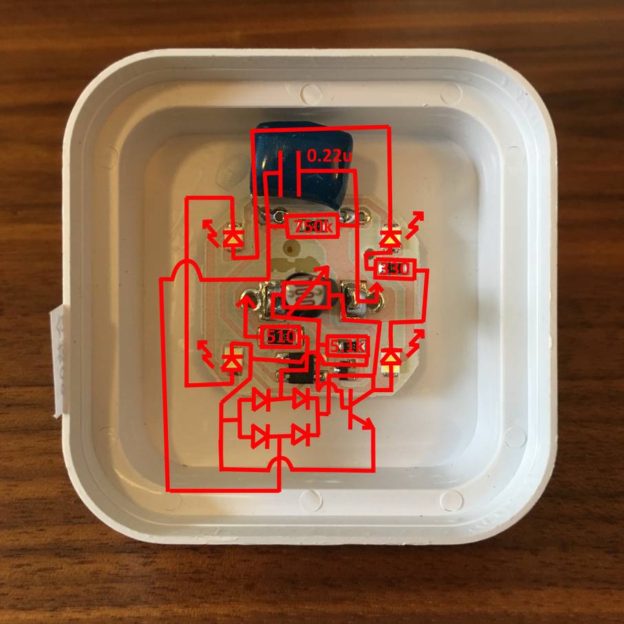
The first step was to figure out what everything was. That was pretty easy. The LEDs are the four yellow boxes at the outside corners of the circuit board. The resistors are all labeled with three numbers "XYZ" where the value of the resistor is XY*10^Z (e.g. 754 --> 75*10^4 = 750k). The squiggly thing in the middle is clearly a photoresistor. The big blue thing is clearly a capacitor that is marked with "400V 224J" where "400V" is the voltage rating of the capacitor, and "224" indicates the value is 22*10^-4 and "J" indicates it has 5% tolerance on the value.

The two big blobs of solder are where the AC power comes in from the wall. And the two ICs were a little more difficult. The small 3-pin device is marked "J3Y". A quick Google search for J3Y turns up the S8050 NPN transistor from Shenzhen City Koo Chin Electronics Limited. I guessed the four-pin device was a bridge rectifier based on the "+" and "-" markings near two of its pins. I was not able to identify its part number though.
Next I traced out the circuit with the continuity checker function on my multi-meter and transferred it into LTSpice for simulation purposes.

I've labeled each section of the schematic to show what each section does.
Current and Voltage Limiters
Resistor R1 and capacitor C1 work together to limit the maximum current and voltage delivered to the load. If the current is too high, the LEDs will overheat and break. If the voltage is too high, then the bridge rectifier will fail and cease to continue rectifying the AC current into DC current.
R1 and C1 must be sized together in order to properly limit the voltage and current supplied to the bridge rectifier. If C1 is too large, then it will never charge, and it will act like a short circuit. In that case, the voltage dropped across the bridge rectifier will be somewhere around V_S*R4/(R1+R4) where V_S is the peak voltage of the mains power. In the USA, V_S is about 120 * sqrt(2) = 169.7 V. All bridge rectifiers have a maximum rating called the "Maximum DC blocking voltage". In cheaper bridge rectifiers, this number is lower, and can be in the range of 50 V. Given V_S = 169.7 V, R4 = 330, and R1 = 510, the voltage across the bridge rectifier would be about 67 V if C1 is too large.
On the other hand, if C1 is too small then it will act like an open circuit and no current will flow through the load. If no current flows through the LEDs, they will never turn on.
Given the maximum voltage desired across the bridge rectifier and the maximum current through the load, resistor R1 can be sized using Ohm's law. Once the value of R1 is known, C1 must be sized so that the current through the load will charge/discharge it at the appropriate rate in order to keep the voltage across the bridge rectifier within an acceptable range.
Finally, the resistor R5 is simply used to discharge the capacitor C1 when the device is disconnected from the wall so that the maximum voltage difference between the capacitor and mains voltage is never more than V_S.
Bridge Rectifier
The bridge rectifier is standard. It forces current to flow in only one direction in the rest of the circuit. It's just four diodes in a single package.
Power Burner
The power burner makes use of a photoresistor to turn off the LEDs when there is ambient light. The photoresistor, marked PSR (for photosensitive resistor) has a resistance of about 2k in a brightly lit room and a resistance of about 25k in a dark room. When exposed to light, the photoresistor decreases its resistance and supplies the NPN transistor with a base current. The base current turns the transistor on, and it conducts current from its collector to its emitter. This starves the LEDs for current (because only a fixed amount of current is available due to the current limiting resistor R1), and they turn off.
When there is no ambient light, the photocell's resistance increases, the base current is removed from the NPN transistor, the transistor turns off, and current flows through the LEDs. This turns the LEDs on at night time.
Since the same amount of current is passing through the cicruit whether the LEDs are on or off, the night light uses the same amount of power all the time. That's why I called this portion of the circuit the power burner.
Load
Finally, the load is just four LEDs and an additional current limiting resistor. I haven't dug into this circuit enough to figure out exactly why a second current limiting resistor is necessary. I think it could be removed without impacting the circuit's functionality. If you know why it's there, feel free to let me know in the comments.
Simulation Results
I also simulated how the circuit works in nighttime and daytime. The first simulation below is the daytime simulation. It shows a maximum of about 14 mA flowing through the collector of Q1 and almost no current flowing through the LEDs.

The second simulation is the nighttime simulation. You can see that it's just the opposite of the daytime simulation: current flows through the LEDs and not the transistor.
